Gouge check: Swarf Machining
Introduction
This topic will explain the options found in the Gouge check tab of the Swarf Machining operation.
Gouge check
The Gouge check tab allows you to specify the surfaces to be checked, how to handle collisions, and what values to use for tool clearances.
Gouge and Excess
The Gouge and Excess options provide you with the ability to completely degouge the swarf path, or you can balance the amount of gouging to the target geometry, for example, for curved surfaces that can't be swarf machined. You can use these options with one or both of Swarf Surfaces and Additional Check Surfaces. There is also an option to gouge check using only the guide curves.
Check
Select one of the following options to gouge check the swarf toolpath.
-
Guide Curves Only - automatically creates a gouge check for the tool against the upper and lower curves. (No other settings are available when selecting this option.
Note: The following options provide further control over the gouge check with the Collision Handling settings.
-
Swarf Surfaces - applies the Collision Handling setting to the swarf surfaces.
-
Additional Surfaces - allows you to select surfaces other than the swarf surface to which the Collision Handling setting applies. Click
 to enable selection
mode, and select the additional surfaces geometry.
 -
Swarf and Additional Surfaces - allows you to apply the Collision Handling settings to both the swarf surfaces and any additional surfaces you select. Click
 to enable selection mode,
and select the additional surfaces geometry.
Collision Handling
The Collision Handling settings provide the following three options.
-
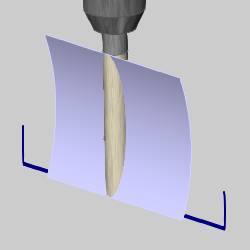
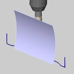
Degouge - removes any gouging from the toolpath by moving the tool out away from the surface (or at a right angle to the plane of the upper and lower curve), using a Gouge Allowance which is a tolerance to the target geometry.
-
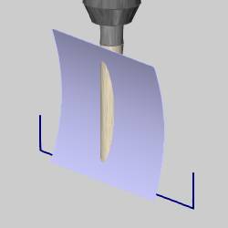
Balance - partially moves to the tool out of gouging by moving the tool out away from the surface. If you compared a pre-gouge checking toolpath with the same toolpath after removing all gouging, balance creates the toolpath in the middle of the two paths. This leaves an equal amount of gouging and rest material compared to the target geometry.

-
Balance Within Allowance - is similar to balance, but allows you to specify the exact amount of allowable gouging using the Gouging Allowance and the Excess Material Allowance.
Note: The following settings become available when selecting Degouge or Balance with Allowance.
-
Gouge Allowance - is the amount of gouging that you want to allow when using gouge checking options. (This is not available for Balance.)
-
Excess Material Allowance - defines how much rest material is allowed when performing the gouge checking calculation. This is only available with Balance Within Allowance. If you don't know an exact value, you can set this value large and then define the exact amount of gouging using the Gouge Allowance.
Avoid by Relinking
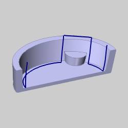
The Avoid by Relinking option allows you to remove gouging toolpath by retracting and linking the gouging toolpath using the current linking options. This can be applied to the Swarf Surfaces and/or Additional Check Surfaces.
Check
-
Swarf Surfaces - applies a retract and link move to any gouges found on the swarf surfaces.
-
Additional Surfaces - allows you to select surfaces other than the swarf surface to which the retract and link move applies. Click
 to enable selection mode,
and select the additional surfaces geometry.
 -
Swarf and Additional Surfaces - allows you to apply the retract and link move to both the swarf surfaces and any additional surfaces you select. Click
 to
enable selection mode, and select the additional surfaces geometry.
-
Check Faces Clearance - determines the amount of clearance around the selected gouge check surfaces.
Avoid by Retracting
The Avoid by Retracting option allows you to remove gouging toolpath by retracting the tool just enough to remove the gouging portion. This can be applied to the Swarf Surfaces and/or Additional Check Surfaces.
Check
-
Swarf Surfaces - applies a retract move to any gouges found on the swarf surfaces.
-
Additional Surfaces - allows you to select surfaces other than the swarf surface to which the retract move applies. Click
 to enable selection mode, and select the additional surfaces geometry.
 -
Swarf and Additional Surfaces - allows you to apply the retract move to both the swarf surfaces and any additional surfaces you select. Click
 to enable selection
mode, and select the additional surfaces geometry.
-
Check Faces Clearance - determines the amount of clearance for the selected gouge check surfaces.
Clearance
These values are used to define the desired clearance distance around the tool Shaft, Holder, and Arbor.
